2010 Toyota Corolla Fuse Box Diagram
Fuses and relay Toyota Corolla 2007-2013
For the Toyota Corolla ((E140, E150) 2007, 2008, 2009, 2010, 2011, 2012, 2013 model year.
Fuse box in passenger compartment.
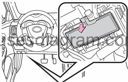
fuse box location.
Under the driver's side instrument panel.
Remove the lid.
fuse box diagram.

legend.
| F1 | (7,5A) Instrument panel |
| F2 | (7.5A) Steering lock system, SRS airbag system, multiport fuel injection sys-tem/sequential ultiport fuel injec-tion system, front passenger occupant classification system |
| F3 | (7,5A) Rear fog lamp |
| F4 | – |
| F5 | – |
| F6 | (10A) Outside rear view mirror defogger |
| F7 | – |
| F8 | (7,5A) Outside rear view mirrors, audio system, main body ECU |
| F9 | (15A) Cigarette lighter |
| F10 | (20A) Sunroof |
| F11 | (20A) Electric windows |
| F12 | (20A) Electric windows |
| F13 | (20A) Electric windows |
| F14 | (10A) |
| F15 | (7,5A) Switch illumination |
| F16 | (10A) Parking lights, tail lights, license plate lights, front side marker lights, multiport fuel injection system/sequential multiport fuel injection system, instrument cluster lights |
| F17 | (7,5A) Ignition switch circuits |
| F18 | (15A) Front fog lamps |
| F19 | – |
| F20 | (25A) Ignition auxiliary circuits supply voltage |
| F21 | (25A) Power door lock system |
| F22 | – |
| F23 | (10A) Stop lights, high mounted stop-light, anti-lock brake system, main body ECU, multiport fuel injection system/sequential multiport fuel injection system, shift lock control system, vehicle stability control system |
| F24 | (7,5A) Data link connector (DLC) |
| F25 | (10A) Back-up lights, charging system, rear window defogger, air condi-tioning system, multiport fuel injec-tion system/sequential multiport fuel injection system, moon roof |
| F26 | (10A) Automatic transmission, main body ECU, electric power steering, elec-tric cooling fan(s), shift lock control system, anti-lock brake system, audio system, tire pressure warn-ing system, vehicle stability control system, cruise control system |
| F27 | (15A) Windshield washer |
| F28 | (15A) Rear screen wash/wipe system |
| F29 | (25A) Windscreen wash/wipe system |
| F30 | (10A) Air conditioning system |
| F31 | (15A) Heated seats |
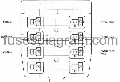
Relay box (driver's side instrument panel).
Remove the instrument panel.
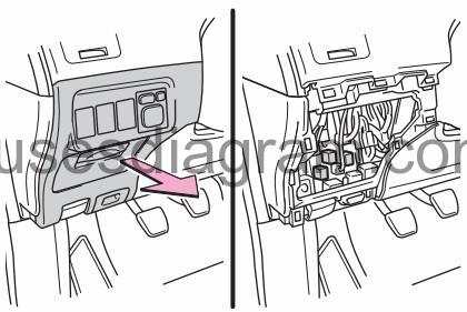
raley box layout.
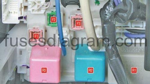
| R3 | Ignition main circuits relay |
| R2 | MTC: AC/heater blower motor relay |
| R1 | Flasher relay |
| F1 | (30A) Electric windows |
| F2 | (30A/40A) Heated rear window |
| F3 | (30A) PWR Seat |
The instrument panel block №8 is located behind the center console, under the instrumen panel.
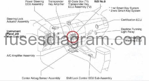
relay box diagram.
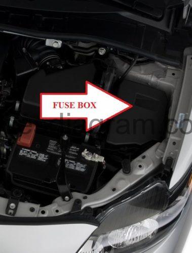
Fuse box in engine compartment Toyota corolla.
fuse box location.
fuse box diagram.
type 1.
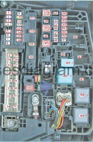
| R2 | Oxygen sensor (O2S) system relay |
| R3 | Injector relay |
| R4 | |
| R5 | |
| R6 | |
| R7 | |
| R8 | Transmission control module (TCM) relay |
| R9 | Headlamp low beam relay |
| F1 | (10A) |
| F2 | (15A) Audio system |
| F3 | (10A) |
| F4 | – |
| F5 | (10A) |
| F6 | – |
| F7 | (7,5A) Engine control module (ECM) |
| F8 | – |
| F9 | (15A) Engine management system |
| F10 | (20A) Steering column lock control module |
| F11 | (20A) Engine management system |
| F12 | (30A) |
| F13 | (10A) Engine control module (ECM) |
| F14 | (10A) Indicators and hazard warning lamps |
| F15 | (7,5A) Alternator |
| F16 | (7.5A) |
| F17 | (50A) Heater blower motor |
| F18 | (50A)ABS/ESP system |
| F19 | (30A) |
| F20 | (40A) Engine coolant blower motor |
| F21 | (30A) Headlamp washers |
| F22 | – |
| F23 | – |
| F24 | |
| F25 | |
| F26 | (50A) Headlamps |
| F27 | (50A) Relay module (RM) |
| F28 | |
| F29 | (30A) Engine management system |
| F30 | (80A) Glow plugs |
| F31 | (60A) Electric power steering |
| F32 | (120A/140A)Alternator |
| F33 | (15A) Engine management system |
| F34 | (10A) Horn |
| F35 | (20A/30A) Engine control module (ECM) |
| F36 | (20A/30A) Engine management system |
| F37 | (30A) |
| F38 | |
| F39 | (30A) |
| F40 | |
| F41 | (30A) |
| F42 | (40A/50A) |
| F43 | |
| F44 | (25A) Auxiliary heater |
| F45 | (30A)ABS/ESP system |
| F46 | |
| F47 | |
| F48 | |
| F49 | |
| F50 | (10A/15A) LH headlamp |
| F51 | (10A/15A)RH headlamp |
| F52 | (10A) LH headlamp |
| F53 | (10A) RH headlamp |
| F54 | (10A) Engine control module (ECM) |
| F55 | (10A) Engine management system |
| F56 | (7,5A) Engine management system |
| F57 | (7.5A) |
fuse box diagram.
type 2.

| Fuse | Ampere | Circuit | |
| 1 | CDS FAN | 30 A | Electric cooling fan(s) |
| 2 | RDI FAN | 40 A | Electric cooling fan(s) |
| 3 | ABS NO. 3 | 30 A | Anti-lock brake system, vehicle stability control system |
| 4 | ABS NO. 1 | 50 A | Anti-lock brake system, vehicle stability control system |
| 5 | HTR | 50 A | Air conditioning system |
| 6 | ALT | 120 A | Charging system, RDI FAN, CDS FAN, ABS NO. 1, ABS NO. 3, HTR, HTR SUB NO. 1, HTR SUB NO. 3, ACC, CIG, METER, IGN, ECU-IG NO. 2, HTR-IG, WIPER, WASHER, ECU-IG NO. 1, AM1, DOOR, STOP, FR DOOR, POWER, RR DOOR, RL DOOR, OBD, ACC-B, FR FOG, DEF, MIR HTR, TAIL, PANEL |
| 7 | EPS | 60 A | Electric power steering |
| 8 | GLOW * | 80 A | No circuit |
| 9 | P/I | 50 A | EFI MAIN, HORN, IG2 |
| 10 | H-LP MAIN | 50 A | H-LP LH LO, H-LP RH LO, H-LP LH HI, H-LP RH HI |
| 11 | EFI NO. 2 | 10 A | Emission control system |
| 12 | EFI NO. 1 | 10 A | Multiport fuel injection system/ sequential multiport fuel injection system |
| 13 | H-LP RH HI | 10 A | Right-hand headlight (high beam) |
| 14 | H-LP LH HI | 10 A | Left-hand headlight (high beam) |
| 15 | H-LP RH LO | 10 A | Right-hand headlight (low beam) |
| 16 | H-LP LH LO | 10 A | Left-hand headlight (low beam) |
| 17 | ETCS | 10 A | Electronic throttle control system |
| 18 | TURN-HAZ | 10 A | Turn signal lights, emergency flashers |
| 19 | ALT-S | 7.5 A | Charging system |
| 20 | AM2 NO. 2 | 7.5 A | Multiport fuel injection system/ sequential multiport fuel injection system, starting system |
| 21 | AM2 | 30 A | Starting system |
| 22 | STRG LOCK | 20 A | Steering lock system |
| 23 | IG2 NO.2 | 7.5 A | Starting system |
| 24 | ECU-B2 | 10 A | Air conditioning system |
| 25 | ECU-B | 10 A | Main body ECU, gauge and meters |
| 26 | RAD NO. 1 | 15 A | Audio system |
| 27 | DOME | 10 A | Trunk light, smart key system |
| 28 | AMP* | 30 A | Audio system |
| 29 | MAYDAY* | 10 A | No circuit |
| 30 | SPARE | 10 A | Spare fuse |
| 31 | SPARE | 30 A | Spare fuse |
| 32 | SPARE | 20 A | Spare fuse |
| 33 | EFI MAIN | 20 A | Multiport fuel injection system/ sequential multiport fuel injection system, EFI NO. 1, EFI NO. 2 |
| 34 | HORN | 10 A | Horn |
| 35 | IG2 | 15 A | Multiport fuel injection system/ sequential multiport fuel injection system, starting system, IGN, METER |
| 36 | ST* | 7.5 A | No circuit |
| 37 | HTR SUB NO. 1 | 30 A | PTC heater |
| 38 | HTR SUB NO. 3 | 30 A | PTC heater |
| 39 | PWR OUTLET/ INVERTER or PWR OUTLET | 15 A | Power outlet |
Source: https://fusesdiagram.com/toyota/fuses-and-relay-toyota-corolla-2007-2013.html
Posted by: kellekellemarolae0271947.blogspot.com
Post a Comment for "2010 Toyota Corolla Fuse Box Diagram"